Towards the mid-80’s LNL made an increasing in the maximum available ion energy, with the purchase of a third electrostatic accelerator, of Tandem-XTU type, by the High Voltage Engineering Company (headquartered in the U.S.). The Tandem, which is a much larger accelerating machine than the 7 MV CN and AN2000, is based on a slightly different operation principle. The High Voltage Terminal (HVT), which exceeds 14.5 MV positive voltage as the maximum operational electrostatic value, is located at the center, and along the longitudinal axis, of a horizontal tank which, in turn, is filled in with insulation gas (SF6 sulfur hexafluoride) at about 7 atm nominal pressure.
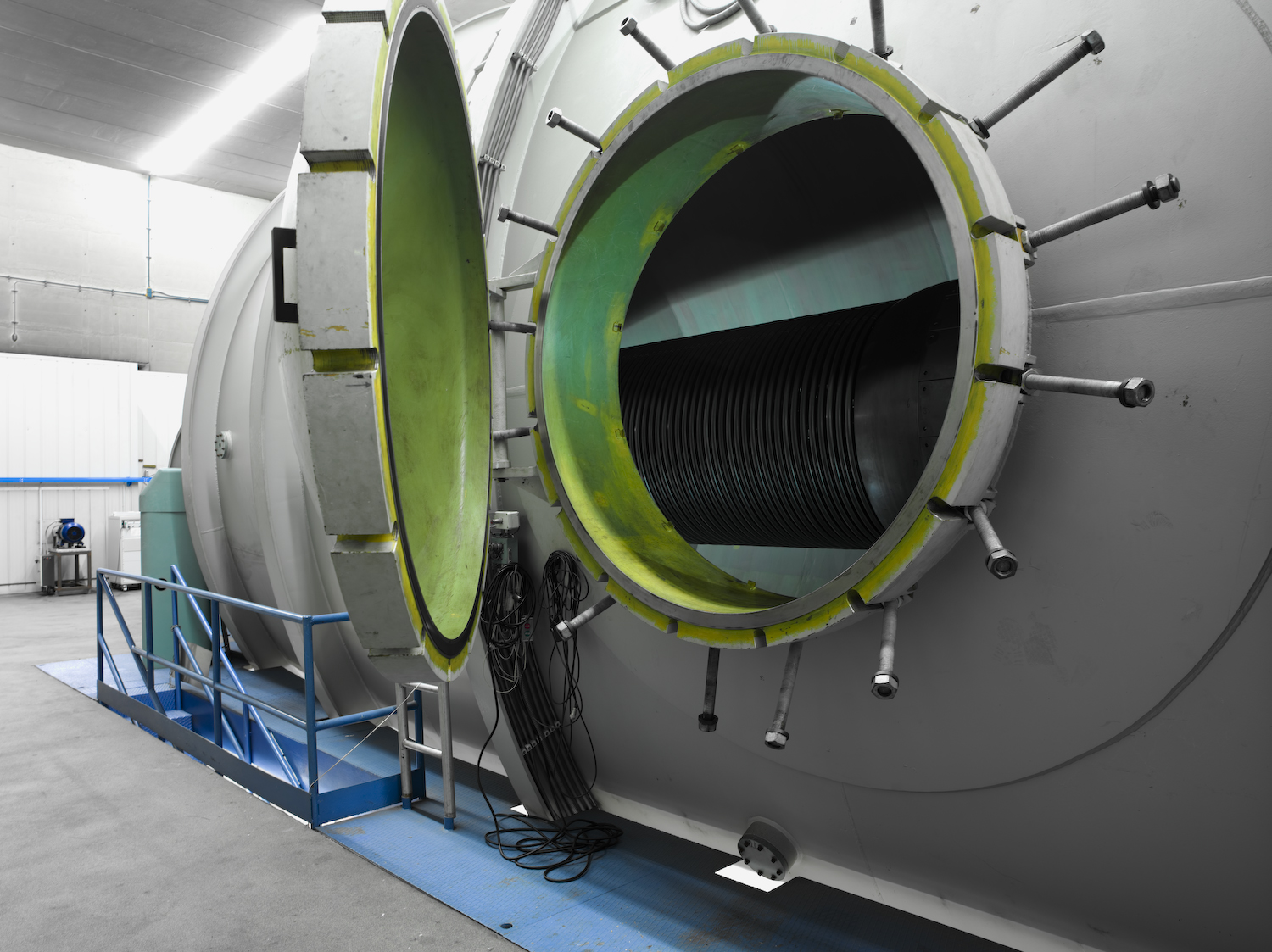
The Tandem-XTU accelerator at LNL: a partial inner vision may be seen in the picture showing both the high voltage terminal and the accelerating column (picture courtesy by Andrea Alessio)
The evacuated beam pipe and the accelerating column, supporting the central terminal voltage, extend from both terminal sides along the whole tank axis length. An operational sketch of a Tandem, showing the main accelerator components, is below.
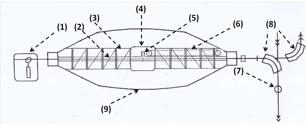
Schematic diagram of Tandem accelerator (courtesy by F. Cervellera). The following elements may be identified: the ion source platform (1); the accelerating pipe (2); the column (3) which supports the high voltage terminal (4), where the ion beam “stripping” station is located (5); the “laddertron” charging belt (6); the beam diagnostic station (7); bending magnets (8); enclosure tank filled in SF6 gas at 7 atm pressure (9).
Ions are generated inside an external source and are extracted with a weakly positive charge state (q = +1). Before entering Tandem ions cross a charge-exchange region in which, by playing on the relative electronic affinity, they receive two electrons from the gas which they interact with (cesium, Cs). The first electron makes the atom neutral again, while the second gives the atom a weakly negative charge (q = -1). With such charge state ions enter the low energy side of the tandem, being attracted (i.e. accelerated) towards the HVT at VT=+14.5 MV.
Inside the metallic terminal (a Faraday cage, as in case of former two electrostatic accelerators) ions pass through a very thin carbon foil (called “stripper”). By absorbing a relatively small beam current fraction, this device can strip the remaining ions by a large number of electrons (up to q’=10 ÷ 20, depending on the ion type and acquired energy), which then leave from the other side of the positively charged HVT with a highly “positive” charged state. These positive ions are hence subject to repulsive electrostatic forces from HVT and undergo a second acceleration step (hence the name “Tandem”) in the second half of the accelerator length. Because of the higher charge state, the energy E= q’·VT acquired in the second half of Tandem length is by far superior to that in the first half.
At the Tandem exit particle are driven, under the effect of both magnetic deflectors and lenses, and distributed by a “switching” magnet towards the selected target station where the relative measurement apparatuses are located. If the magnetic dipole is switched off, the beam may be driven to the ALPI linac enter, in which it undergos a further acceleration step bringing it to even higher energies.
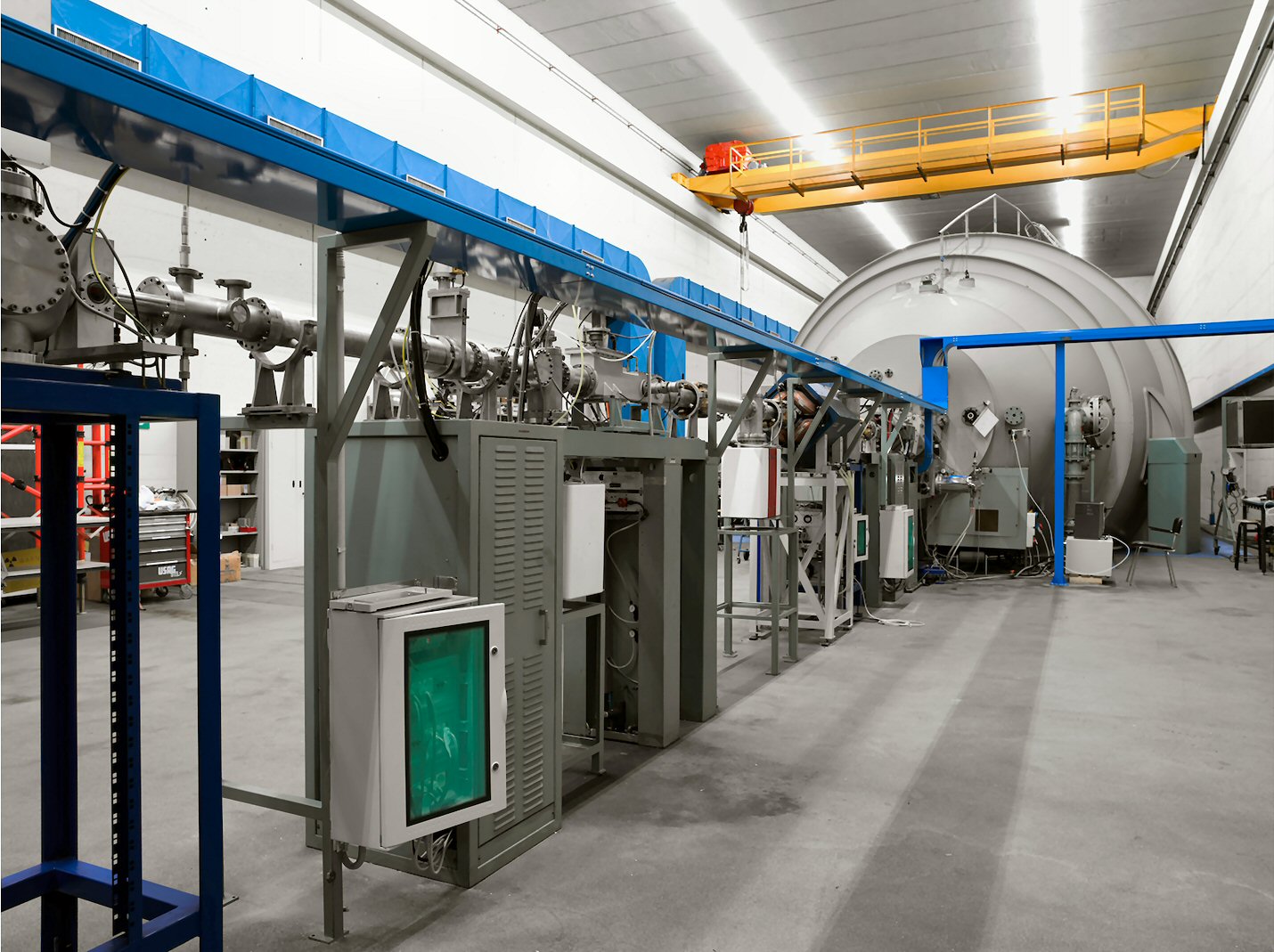
The vacuum pipe at the Tandem accelerator output: the ancillary systems (i.e. void pumps) as well as the megnetic lenses (quandrupoles) may be seen which let the beam focused along the beam axis (picture courtesy by Andrea Alessio).
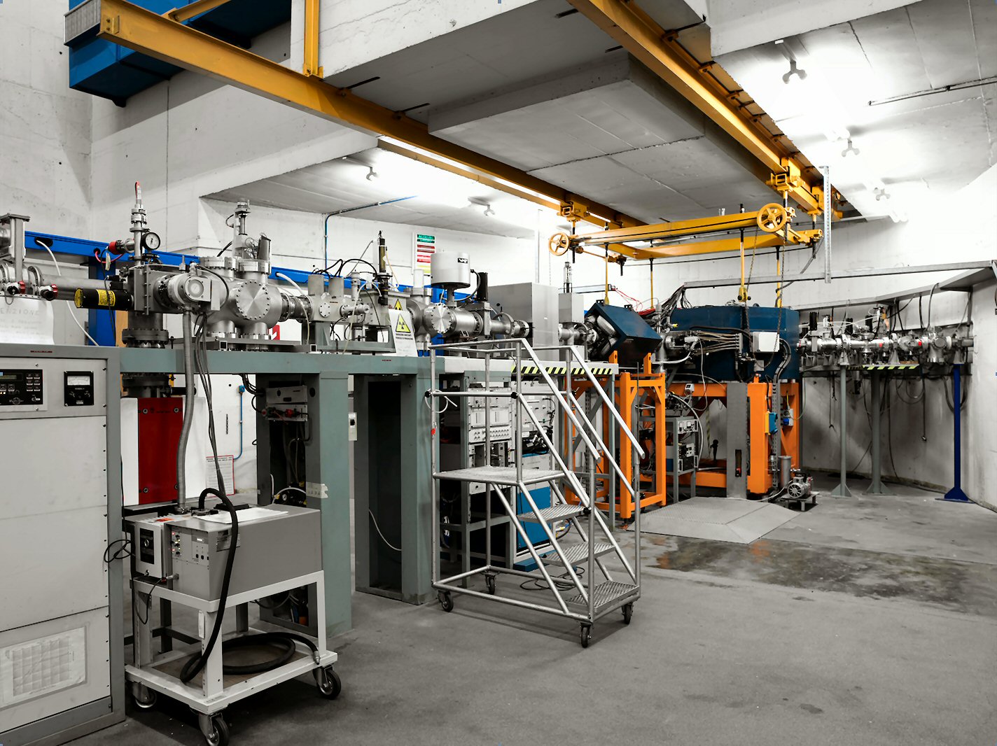
The beam pipe section where the “switching” magnet selects the accelerated beam into one of the channels in the experimental halls. A target station as well as measurement apparatuses are located at the each end (picture courtesy by Andrea Alessio).