The PIAVE linac is also called injector because, unlike the Tandem, may “only” operate in conjunction with ALPI. PIAVE is located into the same shed where the ALPI linac is, adjacent to the beam transport lines to and from the experimental halls. Like ALPI linac, it is based on superconducting accelerating cavities design as well, entirely developed by LNL, and put into operation in late 2004.
Why adding a new injector to the Tandem accelerator (which may operate either in stand-alone or as ALPI injector) to ALPI? The Tandem accelerator, within the high voltage terminal, houses a “stripper” which increases the charge state of the injected ions, in order to increase the final output energy. However, the stripper, made out of very thin carbon foils, has a limited life-time: the higher the beam current hitting the stripper and the heavier the accelerated ion, the shorter the life-time.
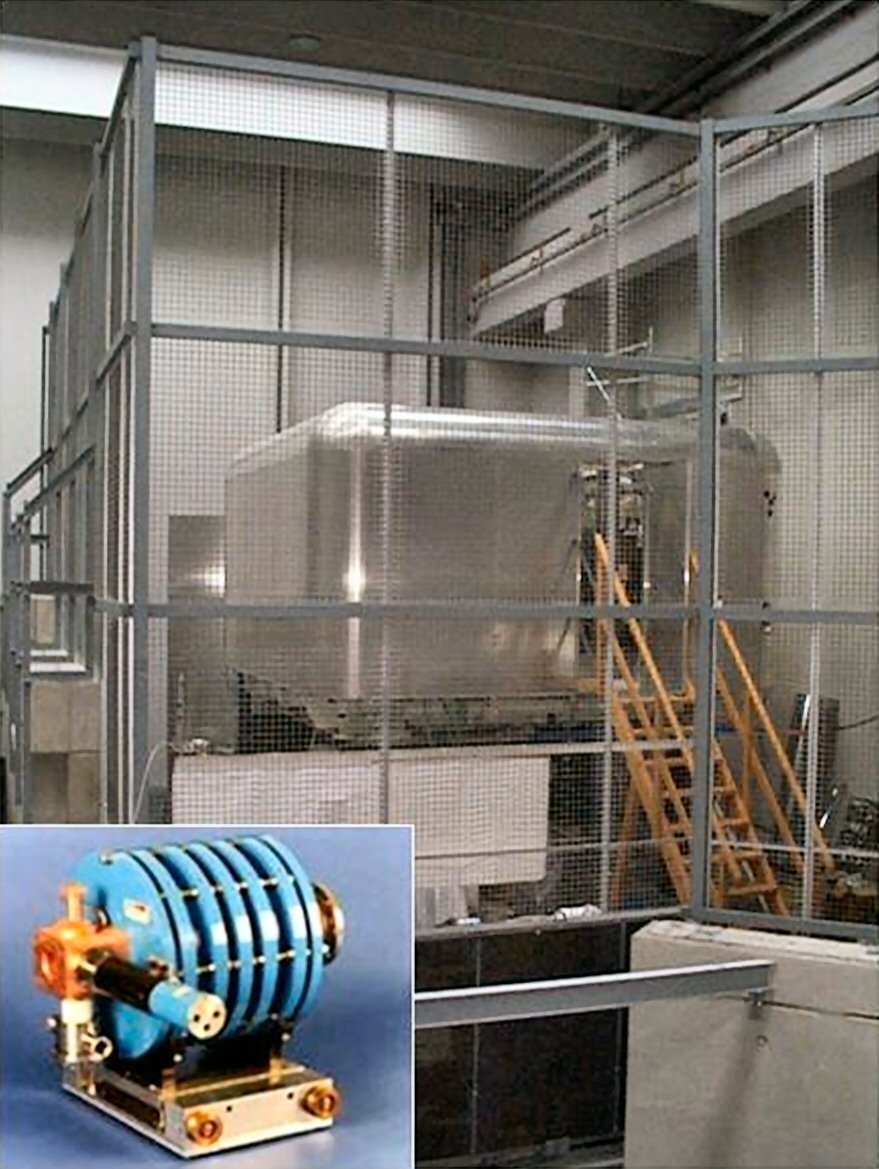
View of the High Voltage Platform (HVP) (working up to up 400 kV), which houses the ECR ion source (small picture in bottom left), surrounded by a metallic electrostatic protection network (sort of Faraday cage)
We remind here that the mass of an ion is roughly equal to the mass number A, where A = Z + N, is the total number of protons (Z) and neutrons (N) atomic mass units (amu) inside the atomic nucleus (the mass of electrons is negligible).Within natural elements, the A-range is between 1 (the lightest one, hydrogen) and value 238 (the heaviest one, uranium). For nuclei with an atomic number larger than A~100, at the beam current levels usually injected inside the Tandem, the stripper foils average life-time is so short to make it unsuitable in practice. When all the 250 stripper foils, available in a special, remotely operated carrier, are exhausted, a Tandem opening is indeed required, in order to replace them.
Such maintenance implies evacuating and recovering the SF6 insulation gas tank, after which the stripper replacement can be carried out in a few days’ time. Then the accelerator tank is closed again and the terminal voltage is stepwise increased up to the operating nominal value. All mentioned operations are usually carried out in 10-20 working days. A prudent use of the stripper station, combined with limiting the atomic mass number of accelerated ions, is therefore essential.
On the other hand, using PIAVE as injector, such an intrinsic limitation on the ion atomic number A does not exist. PIAVE actually operates with a dedicated ECR (Electron Cyclotron Resonance) type ion source, capable of producing ions with a high electrical charge state since their generation (i.e. without the need of pre-acceleration and stripper foil ionization). In PIAVE, the ECR source is located on a High Voltage Platform (HVP), working at about 250 kV positive voltage, which can be increased up to 400 kV if required. The highly charged ions, once extracted from platform, are subject to a repulsive action by the platform itself, which is a first acceleration step. Through a dedicated beam pipe (with magnetic dipoles and quadrupoles), also including a buncher, particles reach three cryostats in a row, lodging 10 accelerating cavities.
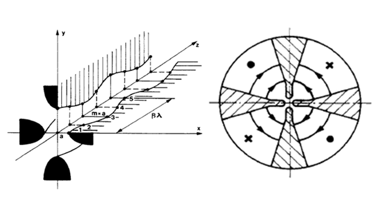
Operation principle for an RFQ. (Left) the four electrodes are Radio-Frequency (RF) driven, polarized in opposite pairs, producing a net focusing effect for the beam crossing the axis of the structure. (Right) a modulation, which is identical on opposite electrodes, but out of phase between the two pairs, imparts an acceleration component to bunches of particles along the structure axis.
Such an ion source system, able to directly supply high charge state particles, is certainly a very important feature for an ion accelerator. A drawback is that the ion energy (provided by the 250 kV HVP) is much lower than the one usually available at the Tandem exit (after having undergone an electrostatic acceleration up to 14.5 MV). Consequently, the quarter-wave resonant cavities, designed to provide acceleration steps to particles having already gained 4 to 5% light speed at least, are not suitable in such a first acceleration part. To overcome such a problem a RFQ (Radio-Frequency Quadrupole) type accelerating structure is thus necessary.
RFQ accelerators have been invented in the former Soviet Union in late 70’s of the last century and, since then, are being rapidly spreading in many accelerators-based laboratories all over the world. The key feature of such a system is to combine, with extreme efficiency, the acceleration function with a strong beam focusing function. This is, in turn, a resonant hollow structure, whose axis – along which the beam runs – is surrounded by 4 electrodes, where an alternating, quadrupole electric field, is generated at the cavity resonance frequency.
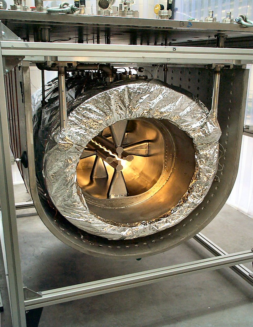
Picture showing one of the two PIAVE superconducting RFQs, inside the cryostat used to test the its RF properties.
If properly designed, the cavity itself generates a peculiar transverse focusing action for ions, by alternating the sign of the focusing lens along the whole structure. To give the structure a moderate, but fundamental acceleration capacity, electrodes are machined in order to provide a modulation profile which is identical for couple of opposite electrode, but phase shifted by 180° between the two electrode pairs.
Such a peculiar machining of the electrodes causes a local deformation of the electric field, in region where the ions beam is located. Although remaining largely transversal, therefore leaving its transverse properties basically unchanged, a longitudinal component (i.e. along beam axis direction) of the local electric field is generated, as a sequence of both weakly accelerating and decelerating fields along the beam axis. If properly designed, such a ripple on the electrode vane is able to provide first of all a net bunching effect on the beam, and then, in a very smooth but increasing fashion, acceleration tool, progressively increasing until the beam exit from the RFQ.
The PIAVE RFQ is unique and basically different from any other one else so far designed. Indeed, likewise all other resonant cavities of LNL accelerators, it also operates in the superconducting regime. The electrode supporting structure is therefore hollow, as are the electrodes themselves, and is kept filled in with liquid He. The pre-acceleration from HVP and the use of an external buncher, penalized by a reduction of the ion current transmitted (by about 30%), allows containing the longitudinal overall length within about 2.2 m. The effort to keep the cavity in stable operating conditions, against slow or rapid variations of its resonance frequency (from minutes down to fractions of second, mainly due to pressure variations of the He bath, or to environmental or mechanical vibration) is therefore easier.
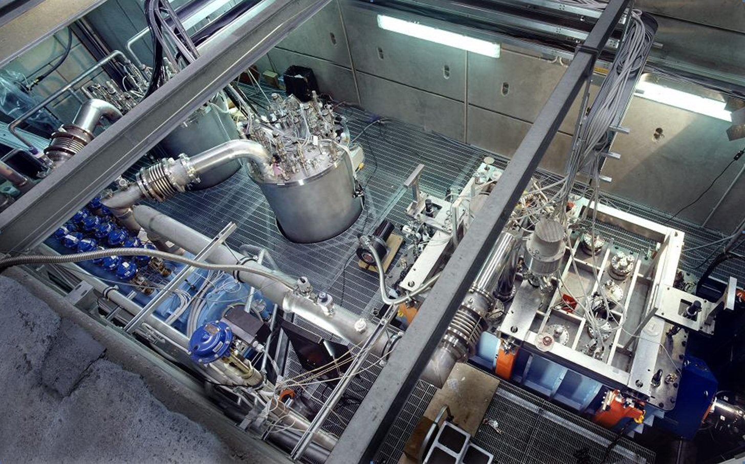
Top view of PIAVE injector which includes the two superconducting RFQs (in the light-blue cryostat) and eight QWR cavities (in the two gray cryostats on the left). The beam comes from the ECR source LEGIS, and runs through the injector from right to left in the picture. A short portion of the beam pipe and a quadrupole focusing lens (in blue may be noted at the bottom right.
Yet it was necessary to split the Superconducting RFQ (SRFQ) into two separate structures (SRFQ1 and SRFQ2) to achieve this goal. The SRFQ resonance frequency is 80 MHz. At the exit of the two superconducting RFQs the ions speed (3.5% of light speed) is enough for an efficient acceleration in 80 MHz RF-driven QWR resonant cavities, very similar in geometry to the first QWR resonators installed in the ALPI linac.
Eight cavities, in two additional cryostats, increase the output energy of PIAVE bunches to match the appropriate energy at the entrance of ALPI. Figure shows a top view of the compact injector PIAVE, where – in particular – the 3 cryostats may be recognized, the one for the SRFQs (blue) and those for QWR resonators.